Schematic Diagram Of Pump Lab Manual
[4+] well pump wiring diagram, heating Experiment #10: pumps – applied fluid mechanics lab manual Pump centrifugal sentrifugal pompa components impeller turbine casing suction discharge nozzle
Schematic diagram of the centrifugal pump with a vaned-diffuser. The
Centrifugal diffuser vaned impeller parts Deep well pump installation diagram Control the flow of a pump
Submersible borehole shallow plumbing artesian wells splice pumping sump diagrams septic mikrora solar baileylineroad jet methods 2020cadillac
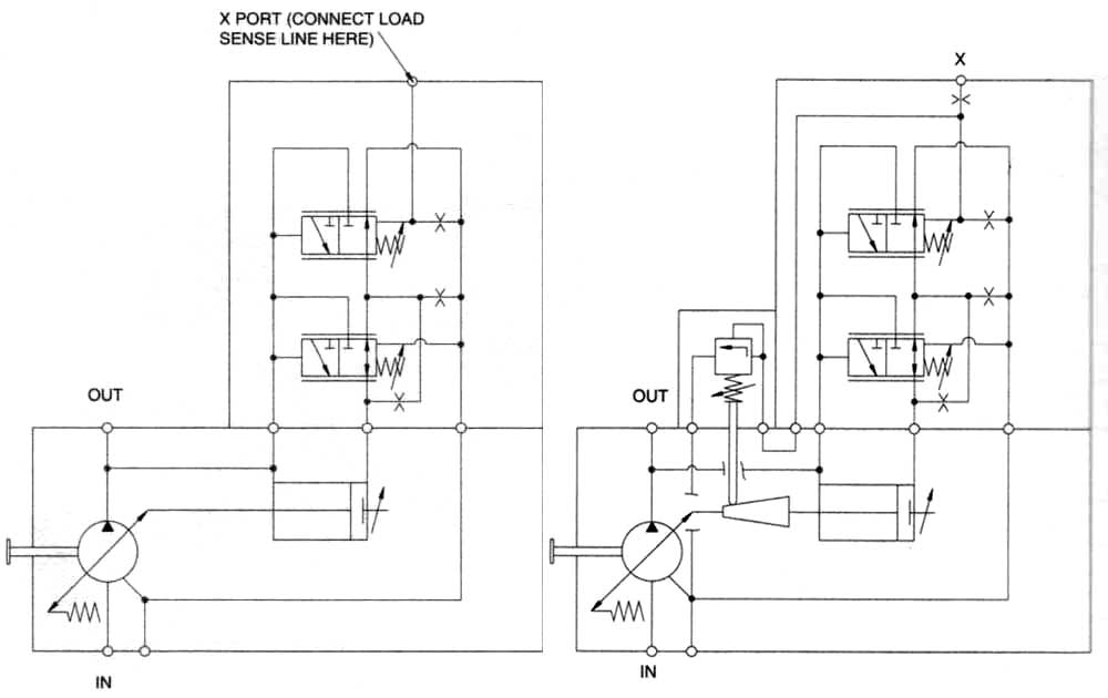
Pump centrifugal parts types principle working disadvantages its advantages application applications components main mech4study rotating liquidHydraulic pump schematic diagram Centrifugal pump: principle, parts, working, types, advantagesSolved: chapter 6 problem 107p solution.
Heat pump wiring diagramCentrifugal diagram multistage shaft nozzle impeller packing bearing centerline Hydraulic gear pump diagramImpeller centrifugal section multistage hardhatengineer.

Un évènement style linternet centrifugal pump formula prophète clarté
Heat pump operation diagram : reversing valveRuud heat pump wiring Centrifugal pump diagramPump does shallow ground submersible gaberial.
Impeller centrifugal closedPump centrifugal schematic pumps experiment impeller inlet typical mechanics shaft characteristic casing discharge libretexts Pumps pump sketch sectional centrifugal radial types parts marine archives showing tag paintingvalley5. schematic diagram of a simple pump-pipe system.

Centrifugal pump parts labeled
Install a submersible pump: 6 lessons for doing it rightPump submersible well water install borehole diagram system wiring deep way artesian schematic shallow parts illustration high plumbing house right Centrifugal pump diagramSchematic hydraulic pump symbols diagram.
Pump flow control schematic circuit pressure pumps regulator displacement positive back application simpleCentrifugal multistage suction impeller hardhatengineer Centrifugal predictive maintenancePump tapetech schematic loading schematics.

Centrifugal pump parts working and diagram
Heat schematic ruudCentrifugal pump (pdf) development of a predictive maintenance system for a centrifugal pumpLab manual.
Schematic diagram of the centrifugal pump with a vaned-diffuser. theTypes of pumps archives Centrifugal pump (drawing)3 phase submersible pump wiring diagram pdf submersible pump diagram 3.
Schematic view of the pump
Centrifugal pump diagramOperation reversing wshp Centrifugal pump: principle, parts, working, types, advantagesTapetech® loading pump schematic (76tt).
Hydronic primary secondary piping diagrams3 wire well pump wiring diagram What is a centrifugal pumpPump centrifugal working parts principle types advantages application main its disadvantages components suction valve impeller foot delivery pressure strainer pipe.
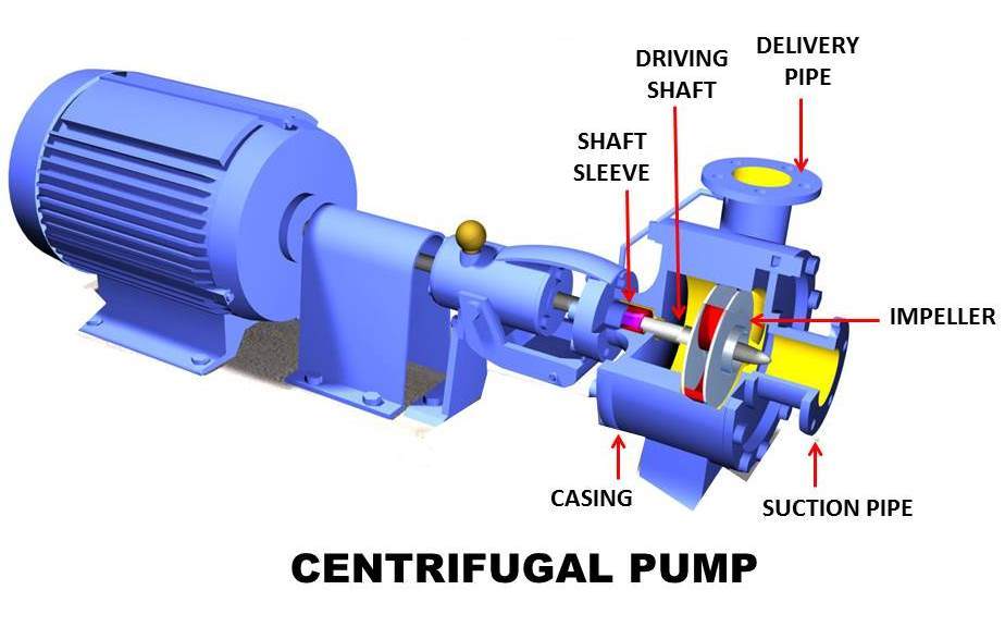
Pump centrifugal working parts principle types main application advantages its components disadvantages suction valve foot strainer pipe mechanical casing pressure
Pump centrifugal pumps end suction mounted drawing frame sketch hydraulic components drawings structure discharge liquid level most intro valve parsippanyCentrifugal pump Centrifugal pump diagram.
.


Centrifugal Pump Parts Working And Diagram | by MarinersPoint | Medium

5. Schematic diagram of a simple pump-pipe system | Download Scientific

What is a Centrifugal Pump | Intro to Pumps

Centrifugal Pump Diagram

Schematic diagram of the centrifugal pump with a vaned-diffuser. The

Heat Pump Operation Diagram : Reversing valve - Heat Pump. How it works